<<< Back
to home page. Bobs Dollops
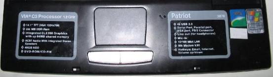
Patriot 3070 307x, EI System 3081, 308x (Generic DSG G320) Disassembly/reasembly.
This document discusses how to fix a common problem with the illustrated laptop range.
Disclaimer
This document contains my dubious opinions about how an amateur reader might do pragmatic 'field repairs'. Repair experts may call them something else. I would not expect a professional service agent to employ these methods because I would expect the agent to have expert tools, skills and replacement parts at hand. I have used and refined these methods on my own laptops and they have consistently worked perfectly and safely for sustained periods under stressed conditions, but obviously for a number of reasons, they may not work for you. Use this entirely at your own risk. If you only want an expert to fix your laptop this is NOT the document for you. If you are an expert, please keep your sense of humour, and put away your flame-thrower.
Aims/Audience
a)
To provide an amateur solution to commonly failed capacitors
on a particular laptop.
b)
To avoid having to send the laptop away anywhere with all
the hassle entailed.
c)
To provide the help needed to open a particular laptop model
without breaking it.
d)
To provide an excuse to explore inside the laptop and learn
- without breaking it.
e)
To provide a 'Blu-Tack' method of reversible dismantling.
f)
To save on costs.
g)
To trade risks in favour of the amateur.
h)
Aspects may help with WEEE (waste electrical electronic equipment)
dismantling.
The problem
Components (capacitors) on these laptops tend to fail (pop)
after a year or two of service *.

The Symptom
The final symptom is that when you plug in power from the external supply with the battery removed the green power LED goes ON, but when you press the power switch the power light goes off again. Before this happens you may or may not get other misbehaviour. One of my machines was fine then died, the other would tend to crash if the laptop was not handled gently while switched on, if you changed the display angle it might crash leaving lost chains in the hard disk. Both machines are now absolutely fine.
Diagnosis
By opening the Fan Cover on the underside you can quickly see if repair is feasible. Look at the bank of 4 capacitors at the edge of the fan bay. If NONE or ONE are bulging or vented* repairing it yourself is feasible. If two or more have failed you will find it very hard to replace these upright capacitors with taller replacements, plus the upright ones are harder to remove safely in the first place. There are 4 more capacitors deep inside that can me more safely replaced if you have 6 hours and the parts. It is assumed that once dismantled the capacitors deep inside will have failed and will likely be bulging or vented. They sometimes fail without visible signs.
Requirements/Assumptions
Time; 6 hours minimum, 2
dismantle, 1.5 repair, 2 reassembly, 0.5 first test.
Skills; Patience,
ability to solder reasonably well. But
no ability to de-solder component leads that pass thru a precious Multi-layer
motherboard with an acceptably low risk of damage beyond repair. Advice; do not
attempt this at all.
Knowledge If
a capacitor in the bank of 4 in the fan bay has failed it is safer and better to destroy the failed capacitor during its removal
than it is to risk destroying the motherboard by timidly trying to desolder the
old capacitor. This is because unsoldering the capacitor is highly likely to irreversibly damage the fragile motherboard. I cannot
stress this point enough. You have been warned. That is why the replacement
part is essential before you start.
Parts; Essential. Pack of 10 x 1500uF 6.3V Electrolytic
capacitors. Farnell order code 114-4672. These are
actually too big (21mm long), ideal
length(12mm).
7/02
insulated wire (if fan bay capacitor replacement required)
Dismantling Tools Small
cross head screwdriver - to undo screws
Small
flat head screwdriver - to prize apart various things
à Blu-Tack - to stick removed screws next to
hole they came from.
Small
electronics industry wire cutters - to snip capacitor leads
3.5mm
Hexagonal nut runner – to remove hexagonal pillars on the back.
(optional)
Heavy duty wire cutters or tin snips - to trim DVD drive bracket
Repair tools; Soldering
iron, solder, clean wet cleaning sponge.
Instructions; See
below
Disassembly
The key to dismantling this laptop is to know how to remove the keyboard. (Step 1.)
Place the laptop before you with lid/display open as if
about to use it normally.
The following list (items 1 to 31) lists the order of parts disassembly.
x1 in the left margin means there is one such
part. This is particularly useful for screws to check all have been removed
before attempting to remove the part they hold. Also it helps you to avoid
leaving out screws when reassembling the computer using the list backwards from
31 to 1. This list was written quickly for my own use from notes made during disassembly
hence its simple layout. No two laptops are identical.
Top access
outside – The following steps are accessed [generally] from the top
(keyboard side) of the case.
1. Keyboard.
x1 a) Press toward you the leftmost latch
along the front edge, gently lift the keyboard corner past the latch far enough
to wedge something underneath it.
Tip: if a key comes off, to put
it on again, place it over exactly where it belongs and press firmly. There is
no need to lift the keys cantilever and fiddle.

b) Press in the other latches from left to right. This way the keyboard
should spring out more with each latch released due to the wedge under one
corner.
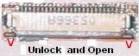
c) Unlock keyboard cable socket to remove flat keyboard cable. Remove
keyboard.
2. Keyboard metal sheet (under the keyboard).
x1 Simply lift out by lifting up the front first and pulling out
tongues along back edge. To re-assemble lift up front and push in tongues along
the back edge first.
3. Under keyboard screws
x7 Do not remove screws covered by Hot-Melt (plastic blob) there is no need to.
Tip:
Blu-Tack each removed screw by the hole it came from.
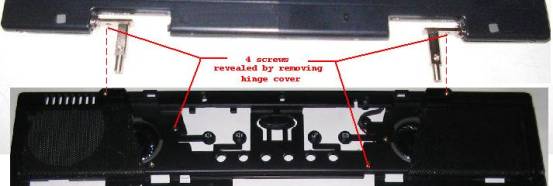
4. Hinge Cover.
x1 This is the piece of plastic between the
speakers that also covers over the display hinges. It is very strong and yet
very flexible, it needs to be both.
a) Shut the laptop display down and turn it around to look at the back
b) Identify the display hinge covers, and the small slots at their edge.
c) With a screwdriver gently lever outward and upward the hinge hoods
(about 2mm) and leave unclipped. Take care not to click them back down.
d) Turn around the laptop again, re-open display/lid more than 90
degrees.
e) Where the hinge cover meets the case along the hinge-line there is a
groove. Place a flat screwdriver in this groove and twist to dislocate the
tongues under the groove so the hinge cover springs upward with the tongues
exposed outside. Start at one end and work across.
f) While lifting the back of the hinge cover (nearest the display) free
of the power and other buttons, slide the hinge cover away from the display to
dislocate the clips under the hinge cover where it meets the keyboard.
5. Screws under hinge cover
x4 remove the 4 screws exposed by the removed hinge cover. 2 are
on the hinge pillars, 2 are around the console buttons/LEDs.
Tip: Blu-Tack each
removed screw by the hole it came from.
6. Hinge Screws
x4 Close the lid, turn round the laptop
again so looking at the back. Identify the screws that hold the display mount
pillars from the back and the underside. Remove them - taking care to
prevent the lid falling off and
breaking. Turn back round again as if to
use the laptop normally and reopen the lid.
Tip: Blu-Tack each removed screw by the
hole it came from.
7. Display plugs
x2 Unplug the 2 leads that connect the
display to the laptop. Where possible avoid tugging the cables, instead pull
the plug housings from their sockets. The most fragile plug is the one on the
left and this plug is easiest to remove without tugging the cable.
Tip; you can rock the
cable a little bit to identify where the plug meets the socket.
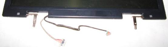
8. Display body
x1 lift out the display cables from their channels, then lift the display out.
9. Display hinge-line Screws.
x3 remove the 3 screws – exposed by
display removal - under the display hinge-line.
Tip: Blu-Tack each removed screw by the
hole it came from.
![]()
Bottom Access outside- The
following parts are accessed from the underside of the case (after display
removed)
10. Battery.
x1
11. HDD plate The
bulging metal plate centre/front - remove 2 retaining screws 1st
x1+2screws
12. HDD
x1 Gently remove by holding the handle,
sliding forward, and lifting out.
13. Screws in Battery Bay
x3
14. Screws: Fan door.
x2
15. Screw in fan compartment corner.
x1
16. Screws under DVD drive
x5
17. DVD drive
x1
18. Rubber rectangular hole covers.
x2 At
front under DVD drive bay. Self adhesive.
19. Screws Concealed by DVD.
x2 Access
thru holes exposed by removing rubber rectangles above.
20. Screw in corner.
x1 Check all underside screws removed. Should be one remaining
in one corner by battery compartment.
Top Access
inside – The following parts are accessed from the topside of the
case (under keyboard)
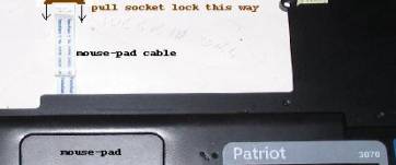
21. Mouse-pad cable
x1 Unlock mouse-pad socket (on motherboard)
first by pulling brown wings firmly toward edge of board, then the thin flat
plastic cable should virtually fall out. The reverse procedure should push the
wings back in firmly after re-inserting the flat cable.
22. Plugs Microphone and Speaker.
x2
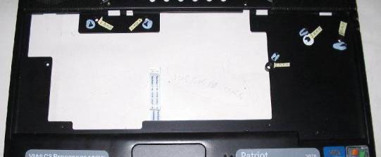
Separate Top/Bottom case apart
23. top case.
Finger nail all round to prize apart plastic clips all round.
x1.
Motherboard removal with cladding attached
24. Screw by mouse-pad socket.
x1 This helps hold the motherboard to
the base of the laptop.
Tip: Blu-Tack each removed screw by the hole it came from.
25. HDD Housing.
x1 +2Screws
This must be removed because it
obstructs motherboard removal.
Cladding removal from motherboard
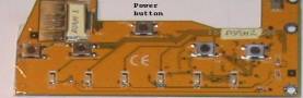
26. Buttons/LEDS board
x1 Lift the right-hand end of the
buttons/LEDs-board to unplug it from the motherboard.
SPECIAL
TREATMENT: It is stuck down onto the motherboards cladding with double-sided
foam tape at the left end, and plugged into the motherboard at the right end.
There is no need to un-stick it from
the foam tape. You can remove and reinsert the plug simply by lifting and
pressing the right end of the board (illustrated below). However when
reassembling align the plug carefully with the socket underneath because firm pressure must be applied to ensure it is properly
plugged in. If you fail to the laptop will not even switch on.
27. Rear hexagonal pillars
x6 These must be removed because they hold
together the top and bottom
metal cladding at
the back of the motherboard.
28. USB Screw (back
of laptop, between the USB sockets)
x1 This must be removed because it holds together the top and
bottom metal cladding around the motherboard.
29. Insulation around modem/Ethernet socket (Black)
x1 Un-stick because it wraps round top and
bottom metal cladding holding them together.
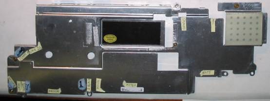
30. Thick top cladding
x1 Unhook from rear connectors and lift off.
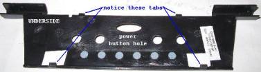
NOTICE;
this thick top cladding forms the visible outer metal surface at
the back of the laptop - the thin inner cladding is behind it. If you forget
which way round it goes the thick/top/outer cladding can be identified by the
circular scrapes around the hexagonal pillar holes where they have been
tightened against the cladding.
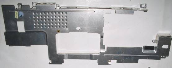
31. Thin bottom cladding
x1 Unhook from rear connectors and lift off.
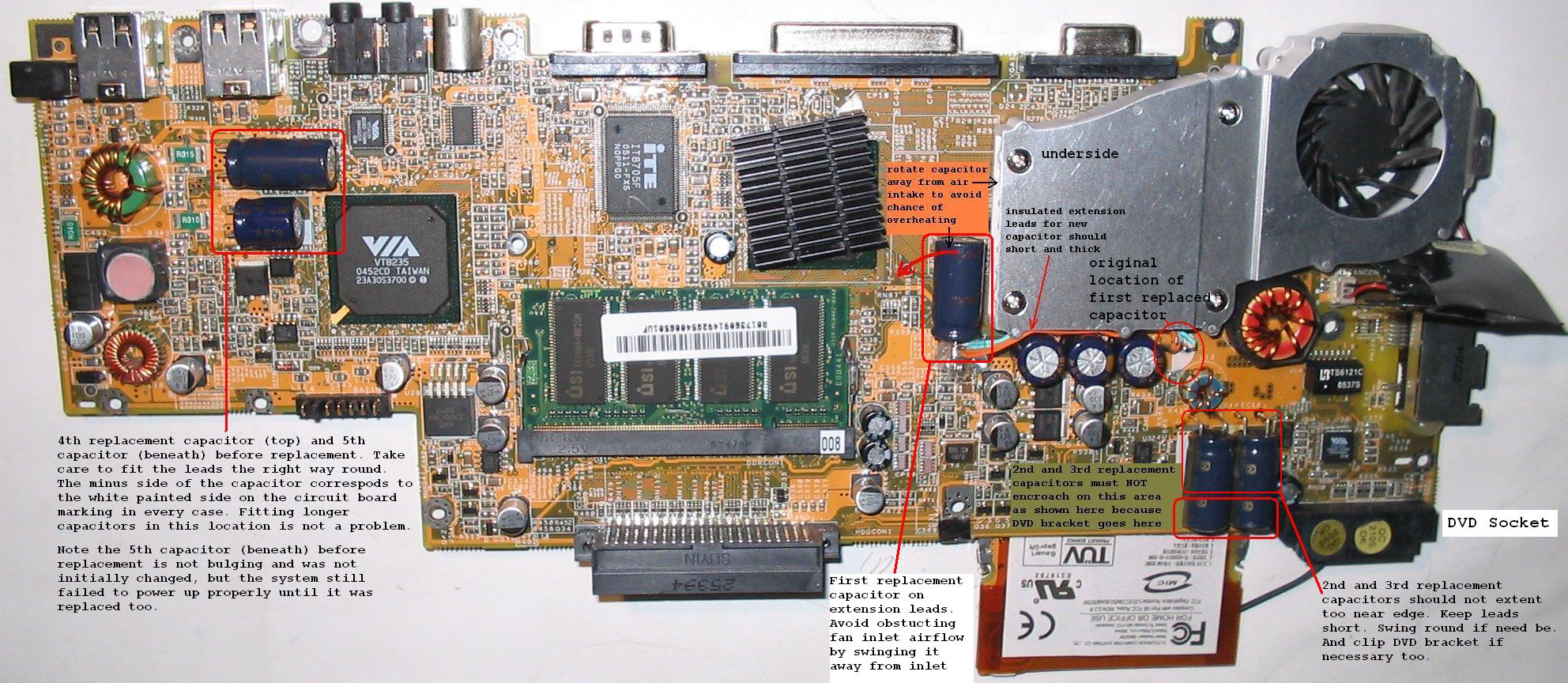
Capacitor replacement.
1) Locate the
vulnerable capacitors.
There are eight such capacitors.
One set of 4, and 2 pairs. as shown below. Click image to zoom.
2) Identify which of the 8 big capacitors have likely failed.
Failed
capacitors are often identifiable because the ends are often bulging or show
any evidence of leaking material because they bulged and then burst. Material
leaked from these capacitors is
probably highly toxic to humans, but oddly it does not seem to damage the
laptop. However if the laptop is soiled it must be gently cleaned. Blu-Tack is good at picking up loose dried material and
dust. (No I don’t have shares in Bostik).
3) Decide if repairable.
If any or all of the 'pairs' of capacitors have failed the repair is possible. Also if ONE of the set of 4 has failed the repair is possible but harder. If more that one of the set of 4 has failed repair is very difficult/impossible with bigger capacitors, and not much easier if you can obtain capacitors the right shape, unless you are highly expert at de-soldering thick thru hole plated circuit boards.
4) Avoid destroying your motherboard by not de-soldering the
old capacitors.
DO NOT EVEN THINK ABOUT ATTEMPTING TO DE-SOLDER THE OLD
FAILED CAPACITORS IT IS ALMOST CERTAIN TO DESTROY YOUR LAPTOP MOTHERBOARD. Instead I recommend cutting off the old
capacitors leaving the old leads sticking out from the board. The new capacitor
leads should be shortened and soldered to these cut leads. For a robust connection you may prefer to
hook the lead ends together before soldering, however bear in mind these
capacitors are bigger and some need flexibility to be twisted a way from other
parts. See step 5 below.
5) Making bigger capacitors fit in the space required.
DVD drive capacitors:
The
capacitor pair near the DVD drive socket is problematic because the DVD
case extends a bracket over the
motherboard where the bigger capacitors are. To save time you must solve this
before putting it all together. You can avoid this problem as follows;-
a) Fit and push the capacitors as far back
from the edge as possible (w/o big force).
b) Position the replacement capacitor(s)
diagonally a little if need be.
c) Only replace one capacitor is only one
is vented/bulging.
d) If possible, fit capacitors of the same
size as the failed ones.
Extra
precautions
e) With heavy cutters - chop off the corner
of the bracket that encroaches. Not easy!!
f)
Stick a small square of insulating tape over the ends of the new capacitors
g) Stick insulating tape over the corner of
the DVD drive bracket.
h) Put some blue tack on the bracket too so
that if it gets close to the capacitor
it will leave an impression you can see
clearly when you come to fit the dvd drive.
Fan bay capacitors;
If one of these should be replaced (because it is vented/bulging) it is
hard to remove
it because
a) Even for experts - it is hard to de-solder
without terminally destroying the motherboard
b) you cannot easily access the leads to
simply cut them. My solution to this is to patiently dismantle the capacitor
itself with small wire cutters and solder insulated extension leads between the
stumps and the new capacitor laying elsewhere in the fan bay. Obviously these
leads should be sort as possible and be made of thick wire capable of carrying
high surge currents. If you do this keep the board clean of conductive debris
as you go and wash your hands afterwards to avoid intoxicating yourself.
6) It
saves time if the disassembled laptop is hooked together temporarily to test
it. Do not connect the HDD or DVD the
first attempt. Just connect the keyboard, display, the power-button board, and
the external power and see if the laptop powers up when you hit the power
button.
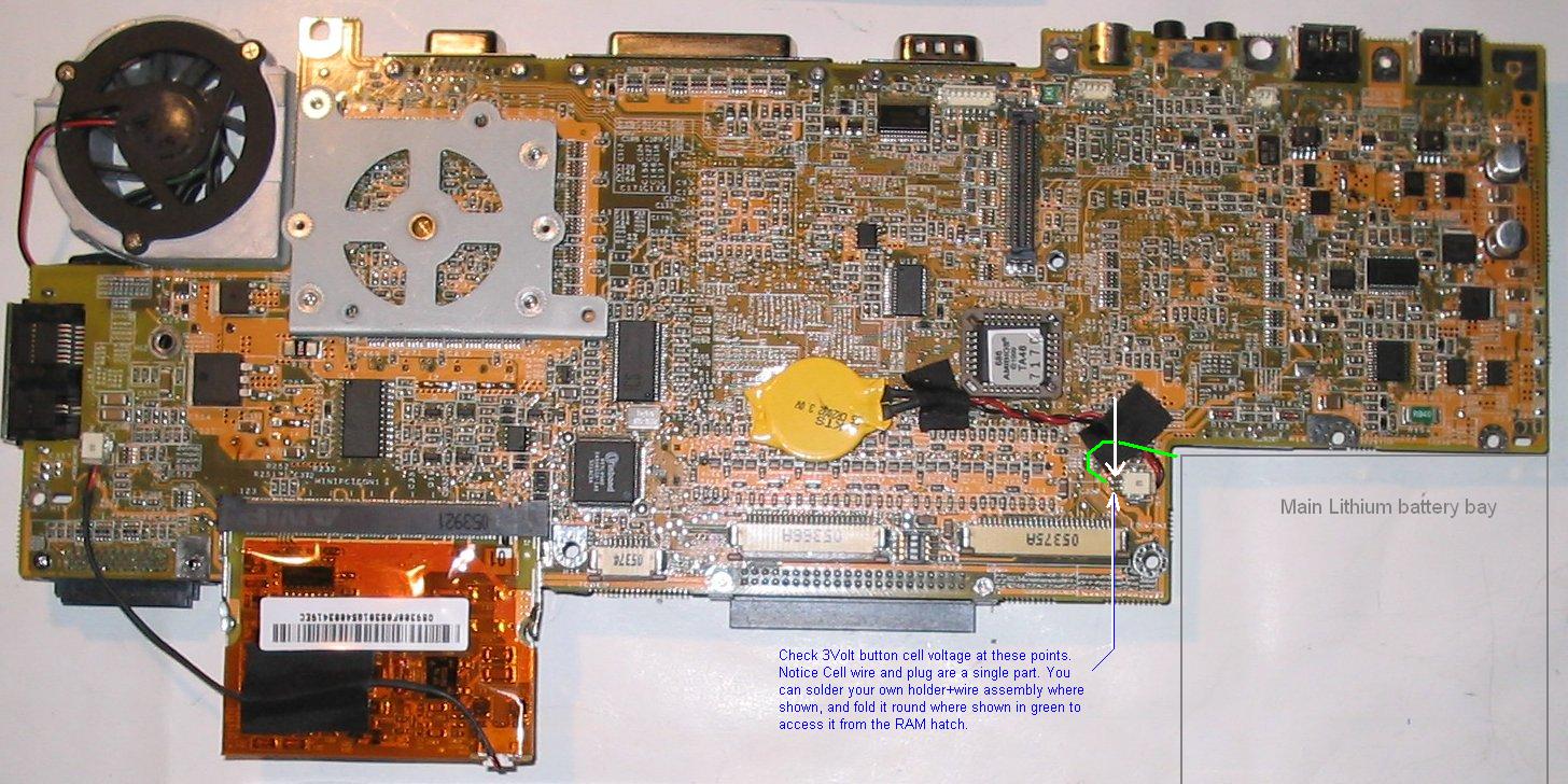
Battery
Check and Replacement.
The yellow object in the picture below is the 3 Volt CR2032
clock battery cell. It may be a different colour on your computer. The battery
and wires with plug are a single removable assembly on the original computer.
The battery cell will probably fail soon after the capacitors fail. So while
the motherboard is accessible I recommend checking the terminal voltage of the
cell at the points indicated by the white arrows. It should be 3V. Take care
not to short-circuit the battery. My battery started loosing the date at
2.1 Volts. A New Cell is 3Volts. You can either buy cells with solder tags on
them that you can solder to, or you can buy plastic holders for plain untagged
cells. Never solder directly to the battery
surfaces. Try RS, Farnell or Maplin. I used the slimmest holder I
could find and attached flying leads twice as long as the old ones so the
battery on the lead could be folded round to the other side of the board for
future access thru the RAM module hatch. It was further insulated with
clear magic tape, and later wedged gently in place at the edge of the hatch so
the RAM could still be accessed. One final note, I did not have a new plug. My
new leads were soldered direct to the back of the motherboard socket
leads. The old battery was left in until the new one was in
place. Only then, quickly remove the old battery by pulling out
the plug.
Reassembly
This is the reverse of the
dismantling procedure.
Taking great care to avoid short circuiting any circuitry with metal parts or tools - it saves time and builds confidence if at regular intervals the partially assembled laptop is hooked together temporarily to test it. The minimum requirement is to connect keyboard, display, power. Do not connect the HDD or DVD on the first attempt. Just connect the keyboard, display, power-button board, and the external power and see if the laptop powers up when you hit the power button.
Restarting and Apparent loss of password
After reassembly a hibernated computer may SEEM to forget the password because it appears the shift key is held down when it is not. Fortunately all you need do is tap the shift key once and retry entering the password. What happens is the computer hibernation remembers the shift-key held down sometimes and so it appears the shift-key is still down while entering the password.
Testing.
Check first with no hard disk or DVD. If the display comes on and complains that there is no boot device that is good. Power off. Fit the HD. Power up. My laptops probably failed a bit early because they are stressed by running at 100% CPU utilization 24/7. They would have failed anyway because I understand the capacitors are likely to be faulty www.badcaps.net . You can stress test your laptop too by downloading from www.wcgrid.org their robust philanthropic software that looks for medical cures. At June 2007 this software it was running on 300,000 PC’s worldwide, and in June 2008 it was running on 400,000 PC’s, and in June 2009; 450,000 devices. At least that many devices are registered. You do not have to run it at 100% you can select any % from 0 to 100 in steps of 10. I would recommend increasing your RAM to 512M or 1G, next time you are in the computer store, but it is not essential.
* About Bulging or Vented Capacitors
Failed capacitors often bulge at one or both ends, or you may see residue of leaked electrolyte. Sometimes they fail with neither indication. See www.badcaps.net for more pictures and expert documentation.

<<< Back
to home page. Bobs Dollops.